搜索
Close this search box.

How to choose the right antenna?

Many hardware engineers, system engineers, or test engineers often face the challenge of selecting suitable antennas for their products. For those in non-communication or electromagnetism-related fields, antennas might seem like “metaphysics.” However, for professionals working with antennas, it is essential to understand how to make the right antenna choice. Let’s explore this topic further.

In the forthcoming article, “Antenna Main Technical Data and Their Meanings,” I will explain the theoretical significance of various antenna data. However, it is not necessary to delve so deeply into the application selection. A basic understanding of the fundamental meanings will suffice.

For example:
The following is the data description of our antenna:

As observed, the key antenna data typically provided include frequency range, gain, antenna material, antenna connector, VSWR, impedance, polarization, directionality, physical size, maximum power, and more. It is essential to identify the most suitable antenna based on our specific requirements and needs.

  1. We must select the appropriate frequency range for the antenna, known as the antenna frequency band. For instance, in the case of a WIFI antenna, we would choose an antenna within the range of 2.4-2.48GHz, where the specified range generally indicates S11≤-10dB.

  1. We need to consider the installation location for the antenna. The choice of antenna size will depend on this factor. For outdoor installations, options like fiberglass antennas and Yagi antennas are suitable finished products. On the other hand, for indoor setups, ceiling antennas, wall-mount antennas, rubber antennas, and similar options are available for selection.

Outdoor antenna:

Indoor antenna:

  1. Another crucial consideration is the directionality of the antenna. This choice involves deciding between a directional antenna, which offers strong gain in one direction and minimal gain in others, or an omnidirectional antenna, which provides similar gain in all directions. For example:

Directional antenna pattern:

Omni-directional antenna pattern:

The radiation pattern may directly affect our practical effect, if we choose a omni-directional antenna, we hope that it has good radiation gain in each direction, but due to the installation environment or pattern defects in the antenna itself will affect the practical use, at a distance limit situation can’t get a signal.

  1. Gain is a crucial factor that directly impacts the link budget (communication distance) of the entire communication. However, it’s essential to note that the gain provided by the antenna usually refers to the gain in the maximum direction of the pattern (dBi) and does not represent the gain in all directions. For omnidirectional antennas, it is also important to consider the “roundness” data, while for directional antennas, checking the “sidelobe” level and front-to-back ratio is recommended.
    According to theoretical analysis and testing experience, a link budget 6dB less will result in a halved communication distance. For instance, if a pair of 2.4GHz wireless modules has a link budget of 100dB (including the antenna gain) and a communication distance of 1km, then a 94dB link budget would correspond to a communication distance of 500m.
  1. Antenna material mainly refers to the material used for both the internal components of the antenna and the radome. The internal components may include common microstrip PCB antennas, FPC antennas, copper antennas, copper tube antennas, spring antennas, and more. These materials play a significant role in determining the antenna’s performance and characteristics.
  1. Antenna connector refers to the specific form of the connector used at the antenna port. Common examples include N-female, 4.3-10 female, SMA, DIN, and others. The choice of the antenna connector is essential for ensuring seamless compatibility with the connecting devices or equipment.
  1. VSWR (Voltage Standing Wave Ratio) is the ratio between the voltage at the peak of the standing wave and the voltage amplitude at the trough. Essentially, it represents the extent of reflection at the antenna port. A VSWR value of 1 indicates a complete match between the feeder and the antenna impedance. An infinite VSWR signifies total reflection, with no energy radiated out. For most antennas, a VSWR ≤ 2 (S11 ≤ -10dB) is considered an acceptable condition. At this point, approximately 10% of the energy is reflected, while 90% enters the antenna.
  1. Impedance: The impedance of the antenna port is represented as a complex number (R+jX), with 50Ω being the typical value. Ideally, the imaginary part should be 0, but in reality, due to the frequency range, some reflections are inevitable. In essence, VSWR is a disguised representation of input resistance.
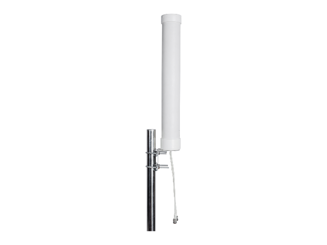
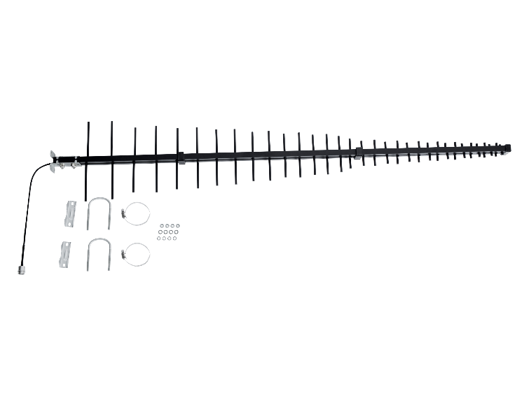
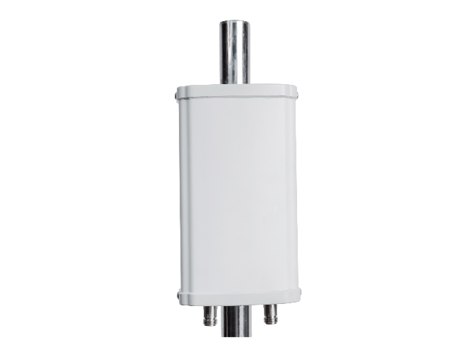
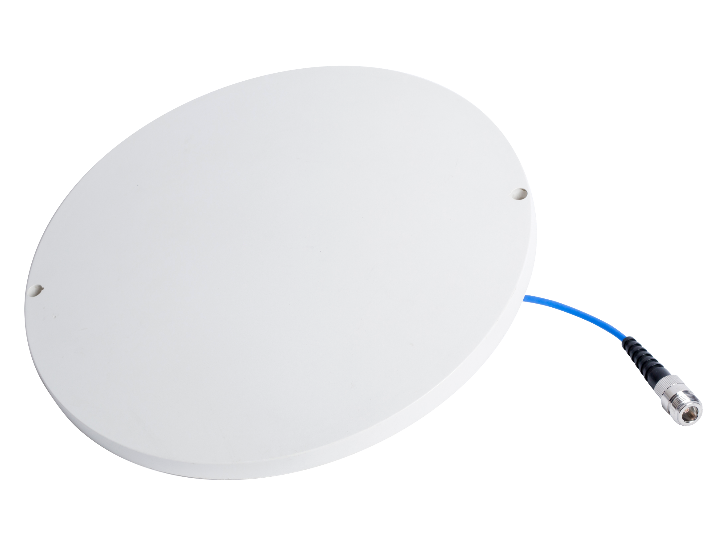
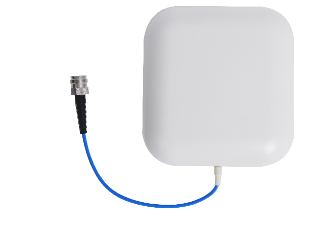
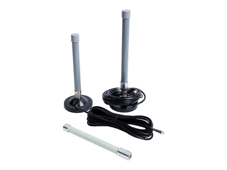
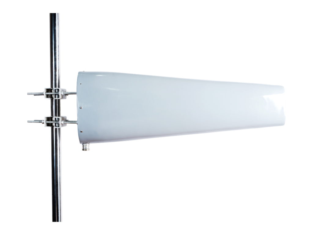
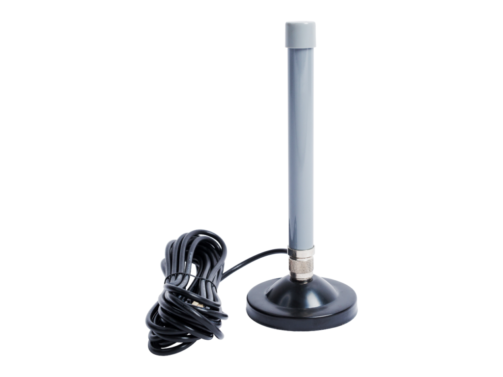
  1. Polarization: Antennas primarily exhibit two types of polarization – linear polarization (vertical and horizontal) and circular polarization (right-handed and left-handed). Linear polarization is the most common and includes antennas such as Ceiling antenna, Yagi antenna, Panel antenna, Small cell antenna, and others. On the other hand, circular polarization is found in antennas like GPS antenna, RFID antenna, spiral antenna, and similar designs.

linear polarization (vertical polarization and horizontal polarization):

circularly polarized antenna:

Ask for more details about Anderson antennas

We will contact you within 1 working day, please pay attention to the email with the suffix”@anderson-tec.com”.

Ask For Customized Antennas.

Please provide the details requirements such as frequency, gain, VSWR etc. We will contact you within 1 working day, please pay attention to the email with the suffix”@anderson-tec.com”.